
Commissioning a Liquid-Cooled AI Rack: Fill, Leak Test and Coolant Sign-Off
Overview
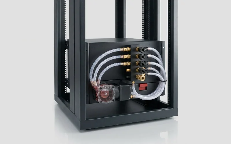
Commissioning a direct-to-chip liquid-cooled rack is a defined sequence – flush, pressure test, fill, purge air, set the CDU, verify chemistry, then soak under load – and every step produces a number that belongs on the sign-off sheet. Skipping steps is how clusters end up with particulate-clogged cold plates, air-locked loops that thermally throttle one chassis, or a slow fitting weep discovered by a leak-detection rope at 2 a.m. The good news: the industry has converged on repeatable practice, documented in the OCP liquid cooling integration white paper, and a careful crew commissions a rack loop in one to three days.
Key takeaways
- Order matters: clean flush first, pressure/leak test second, fill and air purge third, chemistry verification fourth, and only then sustained thermal load – never energise GPUs on an unproven loop.
- Pressure test in two stages: a dry pressure-decay test (air or nitrogen, held typically 30-60 minutes with no measurable drop) before any fluid, then a wet leak inspection at operating pressure with every QD, manifold and fitting checked.
- The standard working fluid is PG25 – nominally 25 percent propylene glycol with demineralised water and a corrosion inhibitor package; do not top up with tap water or RO water of unknown quality, especially in India where municipal water chemistry varies widely.
- Commission the CDU against dew point: supply temperature must stay above room dew point with margin (typically 2-3 C) or you trade a leak problem for a condensation problem.
- Take a baseline coolant sample at sign-off – pH (commonly ~8-10.5 for inhibited glycol systems), reserve alkalinity, conductivity, glycol concentration and particulate – and repeat sampling on a defined cadence.
Before fluid: flush and pressure testing
New piping, hoses and manifolds carry manufacturing debris – flux, chips, oils – that will migrate straight into cold-plate microchannels. Commission clean: high-velocity flush of the facility and rack loops with filtered flushing fluid through bypass jumpers (not through the cold plates), with in-line filters inspected until they come back clean; vendors typically specify flow rate, direction and duration. Then prove tightness dry: pressurise with dry air or nitrogen to the test pressure specified by the CDU/rack vendor and hold, watching for pressure decay – a stable gauge over 30-60 minutes (temperature-compensated) is the usual pass. Dry testing first means a failure is an inconvenience, not a cleanup. Only then perform the wet test: fill, bring to operating pressure, and physically inspect every quick disconnect, gasket and manifold joint, including under-rack drip trays and leak-detection rope routing.
Fill, purge and air-bleed
Fill slowly from the low point with the pump off or at minimum speed, venting from high points – rack manifolds and CDUs provide bleed valves for exactly this. Air is the enemy: trapped pockets cause flow starvation in individual cold plates (one hot GPU in an otherwise cool chassis is the classic signature), pump cavitation, and erratic pressure readings. Circulate at low speed and bleed repeatedly until flow and pressure stabilise and no bubbles reach the vents; degassing a large loop can take hours, and some CDUs automate it. Record the final fill volume – a loop that later needs unexplained top-ups is telling you it leaks. Verify flow balance across chassis (per-server flow or delta-T telemetry) before any sustained load; a chassis running noticeably hotter delta-T than its peers has a flow restriction worth finding now.
Coolant chemistry: what to sign off
Single-phase direct-to-chip loops in AI racks typically run PG25 – a nominal 25 percent propylene glycol / 75 percent demineralised water mix with an inhibitor package – chosen for freeze/biological protection and material compatibility, as described in vendor and industry guidance (for example Schneider Electric’s coolant overview). At commissioning, draw a sample after 24-48 hours of circulation and record: glycol concentration (refractometer), pH (inhibited glycol systems commonly specified around 8-10.5), reserve alkalinity (ASTM D1121), conductivity, and particulate/appearance. These numbers are your baseline; periodic samples (commonly every 3-6 months) are compared against them, and drift – falling pH, depleting reserve alkalinity, rising conductivity – is early warning of corrosion or contamination. Indian sites should be strict about make-up water: use demineralised or vendor-approved premix only, and store it sealed – monsoon-season humidity and dust will contaminate an open drum. Wider water-quality context is in liquid cooling in India: CDUs and water quality.
CDU commissioning and dew point control
With the loop full and clean, commission the CDU: verify pump rotation and duty/standby failover, set the TCS supply temperature per the platform spec (modern GPU cold plates typically accept warm water; your vendor’s figure governs), confirm flow rate at design, and check the approach temperature across the heat exchanger against the datasheet – a high approach on day one means air on one side or fouling already. Critically, interlock supply temperature against room dew point: the CDU must never supply coolant below dew point plus margin (2-3 C is common), or condensation forms on cold plates and hoses – a real risk in humid Indian summers if the room’s humidity control is marginal. Test alarms end-to-end: leak rope detection to BMS/DCIM, low-flow, high-temperature, and loss-of-pump events should page a human, not just light an LED. CDU sizing itself is covered in our CDU sizing guide.
Thermal soak and handover to burn-in
The final commissioning step is sustained load: run the rack’s GPUs at high power (HPL-class load) for at least 24 hours while logging supply/return temperatures, per-chassis delta-T, flow, pressure and any weep at fittings – this is where marginal QDs and hose crimps reveal themselves. Fold this into the wider burn-in campaign so thermal and compute validation share one evidence pack, and file the loop documentation – fill volume, test pressures, chemistry baseline, CDU setpoints, alarm test results – into the acceptance record.
Liquid loop commissioning sequence
| Step | Method | Pass criterion | Record |
|---|---|---|---|
| 1. Clean flush | High-velocity filtered flush, bypassing cold plates | Filters return clean; vendor duration met | Flush certificate, filter photos |
| 2. Dry pressure test | Air/N2 pressure decay at vendor test pressure | No measurable decay over 30-60 min | Test pressure, duration, gauge log |
| 3. Fill and purge | Low-point fill, high-point bleed, slow circulation | Stable flow/pressure, no bubbles, balanced delta-T | Fill volume, per-chassis flow |
| 4. Wet leak inspection | Operating pressure, inspect every joint and QD | Zero weeps; leak rope dry and tested | Inspection sheet |
| 5. Chemistry baseline | Sample after 24-48 h circulation | Glycol %, pH, RA, conductivity in vendor window | Lab/field results as baseline |
| 6. CDU setpoints + alarms | Set supply temp vs dew point; trip every alarm | Dew point margin held; alarms reach on-call | Setpoint sheet, alarm test log |
| 7. Thermal soak | 24 h+ GPU load at design power | No throttling, no weeps, stable approach temp | Telemetry archive |
Frequently asked questions
Can we skip the dry pressure test and just fill carefully?
No. A wet-discovered leak means draining, drying and possibly de-energising neighbouring equipment; a dry-discovered leak means tightening a fitting. The dry decay test is minutes of effort with nitrogen or clean dry air and catches the majority of assembly faults before they can do damage.
What is wrong with using RO or tap water for top-up?
Tap water carries chlorides and hardness that attack copper loops and foul microchannels; even RO water without inhibitors dilutes the inhibitor package and shifts pH out of specification. Top up only with the vendor-specified premix or demineralised water plus inhibitor per the fluid supplier’s ratio, and log every top-up – volume trends reveal slow leaks.
How cold should the coolant supply be?
As warm as the platform allows, not as cold as the CDU can make it. Warm-water cooling (supply temperatures in the 30-45 C range on many modern platforms, per vendor specs) improves chiller-free economisation and keeps you far from dew point. The binding constraints are the GPU vendor’s cold-plate inlet spec and dew point plus margin on the low side.
Who signs the coolant chemistry certificate?
The commissioning agency or integrator signs the results; your facilities engineer countersigns after witnessing the sample draw; and the fluid values should be attached to the acceptance certificate. If an AMC covers the loop, the AMC provider should accept the baseline in writing – it defines the state they are contracted to maintain.
How often should coolant be re-sampled after commissioning?
Common practice for water/glycol loops is every 3-6 months, plus after any component replacement, unexplained top-up, or temperature excursion. Compare against the commissioning baseline rather than absolute limits alone – the trend is the early warning. Day-to-day monitoring practice belongs to your Day-2 operations runbook.
Ready to deploy?
Talk to an RDP architect about power, cooling and lead time.